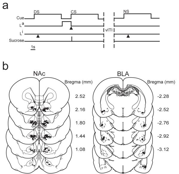
Figure 1.
a) Schematic of the operant task. During sessions, one of two trials was presented, the DS or NS. The DS was presented for 6s, after which the active lever (La) was extended. Responses on the La resulted in sucrose delivery and CS onset (6s). Responses during the NS had no programmed consequences. The inactive lever (Li) was always present. Black triangles denote a lever response. b) Histological representation of electrode and cannula placement. Left diagrams show the NAc placements of electrodes at recording. Right diagrams illustrate the tip of the microinjector placed into the BLA cannula. Images are adapted from (Paxinos and Watson, 2005).

